Governance by those who do the work.

Friday, December 19, 2014

Precision Roughness Plate

John Cox has completed the difficult job of milling the aluminum plate to make a precision rough surface!  Its average (also the root-mean-squared) height of roughness is 3 mm.  Cutting the MIC-6 aluminum broke several end mill bits.  Reducing the depth-of-cut to less than 1mm, it took 6 hours on a ShopBot CNC mill.

While MIC-6 turned out to be difficult to machine, its cut surfaces are highly reflective and should hold radiative heat transfer to a minimum.

Next, I will attach the heating elements and temperature sensor to the plate and program the microcomputer to take measurements and store them.  The first measurements will be of natural convection.  After that it will be suspended in the wind tunnel for measuring forced convection.

Saturday, November 8, 2014

Convection Measurement Electronics

Pictured are two electronics boards constructed for measuring convection from an instrumented plate.  The small board on the left will measure pressure, humidity, and temperature of the air at the wind-tunnel intake.

The larger board contains power supplies, heater control and drive, signal conditioning, a three-digit 7-segment display, and a STMicroelectronics ARM STM32F3 Discovery board.  The ARM computer is the green board.  It will control the heater embedded in the plate and collect the sensor data during experiment runs.

The two yellow blocks connected by black cables to the larger board are receptacles for Lenovo laptop 20 Volt power supplies.  The large black object is a heat sink for the heater drive.

The other photo shows the wiring on the back of this board.  Although there are many soldered connections, most of the components are mounted on 16-pin DIP headers seen on the front side.  These are plugged into prototyping sockets with insulation-displacement contacts.  Connections made using 30 AWG wirewrap wire.  This technology was sold by 3M in the 1990s.  I don't think it is sold commercially any more.

Friday, August 29, 2014

Greater than 4 m/s in wind-tunnel!


 Working on the wind-tunnel, I noticed that wind blows outward from the fan only directly in front of the fan blades.  There is an inward flow from those areas not directly in front of the blades.  I created a new cowling which wraps around the perimeter of the fan to cut off flow from those areas. The result is a speed increase in the chamber from 3.6 m/s to 4.1 m/s, a 14% improvement!


In mapping the flow field in chamber it turns out that the boundary layer develops quickly with distance from the front edge.  This chamber will be barely large enough  for the 30cm x 30cm plate; its boundary layer will impinge on the leeward corners of the plate.

Monday, August 25, 2014

Convection Instrumentation

My first design for the plate heater involved building a 100+ Volt power supply.  Since then I have realized that by stacking two laptop power supplies, a 40.V supply could be had inexpensively.  Each supply is rated for 90.W, so they have ample power for the heater.  The maximum current the heater will draw is 2 Amps; in order to account for wire losses, the voltage across the heater will be sensed by another pair of wires.

The first design had a digital-to-analog converter driving the gate of a SD220 n-channel MOSFET, and its output driving the gate of an IRF9520 p-channel power MOSFET.  The forward gain of the circuit was over 1000.  With such high gain, only a few of the DAC codes would cover the range of planned drive levels for the heater.  So I have ballasted both MOSFET source terminals with resistors to lower their gains.  The SD220 guarantees its threshold only to be less than 3.V, but the STM32F303VCT6 microcontroller DAC output only drives up to 2.8.V, so an op-amp is needed to servo the source resistor to the DAC output voltage.  Servoing the IRF9520 current to be proportional to the SD220 current means that, within its operating range, the current is set by the DAC.  Multiplying that current by the voltage sensed across the heater measures the power delivered to the heater.

The design includes electronic temperature, humidity, and air pressure sensors.  The only relevant condition not being sensed is windspeed in the chamber.  I investigated many windspeed sensing technologies, but techniques for measuring below 4.m/s require laminar flow, affect the flow, are too large, are inaccurate or are prohibitively expensive.

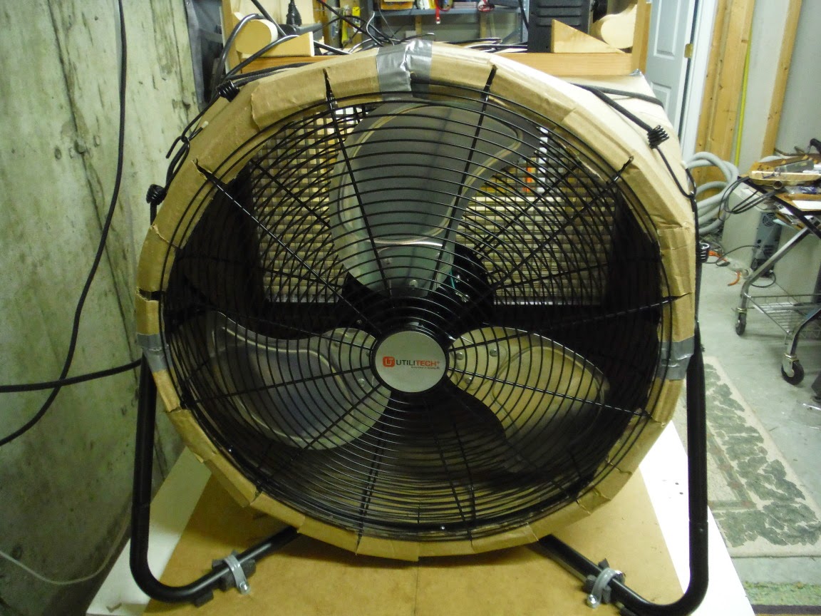
With a variable transformer I measured consistent windspeeds in the tunnel from 4.m/s down to 1.m/s.  The windspeed varies smoothly with the rotation rate of the fan.  Instead of trying to servo the fan's rotation rate, I will measure the rate of the fan blades interrupting an infrared beam between a LED and photo-transistor on opposite sides of the fan.  Calibrating the relation between windspeed (as measured by an impeller anemometer) and the fan's rotation rate will enable tracking of windspeed over small variations in rotation rate.

Saturday, August 2, 2014

Wind Tunnel Success!

My first tests of the wind tunnel were not encouraging.  This morning I turned the fan around so that it draws air through the wind tunnel instead of blowing (I left the egg-crate between the test chamber and fan cowling) and the results were excellent!

At the open end of the test chamber the flow rate was uniformly 3.6 to 3.7 m/s.  Taking measurements at the walls at increasing distance into the chamber, the flow rate gradually dropped as would be expected for the developing boundary layer.   Rotation in the test chamber was nearly unmeasurable.

Because the fan switch is now inside the cowling, I set the switch to its highest setting and plugged the fan into a variable autotransformer.  Adjusting it so that the pitch of the fan dropped about one octave (1/2 frequency), the flow rate dropped to 2.1 m/s, slightly more than half.  So the flow rate is a roughly linear function of fan speed.  I intend to put an opto-interrupter sensor on the fan to monitor its speed precisely.

I also ran a test without the egg-crate.  Uniformity was not as good, and there seemed to be some rotation in the test chamber.

Because I can't achieve 10 m/s in the tunnel, I must make my convection measurements at lower speeds.  This means that I must get more accurate measurements and estimates for the other modes of heat transfer than if the speed were higher (in order to achieve the same experimental accuracy).  Lower speeds also mean less heat flow; so the block of aluminum I bought for the plate is thicker and will have longer settling times than is needed.


Here is the tunnel in operation with the anemometer showing 3.7 m/s:

Thursday, July 31, 2014

First test of Wind Tunnel

As described in http://people.csail.mit.edu/jaffer/SimRoof/Convection/Measurements, I am trying to construct a wind tunnel in order to measure forced convection from a rough plate.

Yesterday I assembled my cardboard fan housing onto the test chamber. It was difficult to do alone; the process ended up involving several bungee-cords.  With only 27mm of flow-straightener (will eventually be 150mm), I was not expecting smooth flow.

Comparing operation between the lowest and highest fan settings, there was only a 20% increase in flow through the chamber.  So I will not achieve my original target of 10m/s flow.  Perhaps I can achieve 5m/s.

Between the fan and the flow-straigtener I put two interlocking boards at right angles to block the substantial rotational flow from the fan (the boards also eased assembly).  The flow was thus split into four quadrants, each with substantial rotational flow.  The anemometer showed 4:1 variations of flow in each quadrant of the chamber.  I was able to easily sense the flow variations by moving my hand around inside the chamber.

I need to cut the interlocked boards so that they aren't as deep, and add additional radial vanes to try to eliminate the gross pressure variations before the flow enters the flow-straightener. Alternatively, would a second flow-straigtener at the fan work better than radial vanes?


For the next test I removed the interlocked boards for suppressing the rotation.

In the test chamber the flow pattern was simpler.  Fairly uniform wind speed in a ring around the center.  It drops precipitously in the center and at the left and right edges.  The momentum of the rotating air coming out of the fan drives it to the outer rim, depleting the center.

Rotation in the test chamber was at low levels.  So even a short depth of egg-crate stops the rotation, but does not equalize the flow across its width.  This suggests that there should be egg-crate directly in front of the fan to stop the rotation, an airspace to let the air pressure equalize, followed by egg-crate to straighten the flow (leading into the test chamber).

I performed two other tests.  When I removed the egg-crate, the flow was slightly stronger but the rotation was much higher in the test chamber.  Putting window-screen between two layers of egg-crate cut the flow by nearly half, but did not make the flow uniform.

Sunday, April 6, 2014

Recurrence for Multidimensional Space-Filling Functions

"Recurrence for Multidimensional Space-Filling Functions" is the culmination of many years' interest in space-filling curves and functions.  The recurrences result from a de novo analysis that was more engineering than mathematical.  Instead of trying to characterize all possible curves or base patterns, I focused on finding a cell algorithm for all ranks and side lengths (greater than 2) and making that work with a self-similar recurrence subject to scaling laws I discovered from previous implementations.

That cell algorithm is "serpentine".  It turns out that both the Peano and Hilbert (multidimensional) space-filling curves are instances of my recurrence working on serpentine patterns.

From there I generalized the alignment function.  In the alignment function there were degrees of freedom for diagonal-corner cells (with odd side lengths) which were easy to employ to improve their isotropy (Peano curves are anisotropic).  There are degrees of freedom for adjacent-corner cells of rank greater than 2, but deeper analysis will be required to understand them.

While the alignment function seems to work for all serpentine cells (I verified thousands of combinations of rank and side-length), this is not yet proven.  And Figure 20 at the end of the paper shows a non-serpentine 3x3x3 adjacent-corner cell whose symmetrical version works with my alignment function, but whose asymmetrical variant does not.  Future explorations should determine if that asymmetrical cell itself is valid, and discover the constraint on cells if that is not the case.

The non-terminating recurrence is elegant but was tricky to discover because its truncated form returns coordinates at the center of sub-cells rather than at their origins as the integer recurrence does.

The centered form was accomplished by generalizing the offsets I earlier discovered for centering the Peano curve.

Hereditary Dislike of Family

The extensive genealogy work my spouse has done has barely penetrated one branch of my family, and it's not because it lacks descendants! Unlike the other relatives, the ones in this branch admit to knowing little or nothing about their parents' and grandparents' generations. Many in this branch have not responded to our inquiries; two have told us to never contact them again.

So why does antipathy towards relatives seem to be concentrated in this line?  An interesting idea is to consider the evolutionary consequences of a heritable dislike-your-family trait.  Such a trait seems present in the life cycles of some social species where only a minority of adults leave their clans.  While this trait would, on average, probably reduce the survivability of the individuals expressing it, that could be outweighed by the increased dispersion of the clan's genes.

Such a trait could have more than one cause.  One possibility is the types of mental illnesses which often result in the breakup of families.  Schizophrenia in particular tends to manifest in late adolescence, the time when individuals become fertile and able to live independently.  Separation from the clan at that time maximizes their chances of mixing their genes with other clans in offspring.

If mental illness benefits the species by increasing genetic diversity (which is evidenced by its global occurrence), then mental illness is an integral and persistant part of the human genome.