Governance by those who do the work.

Friday, August 29, 2014

Greater than 4 m/s in wind-tunnel!


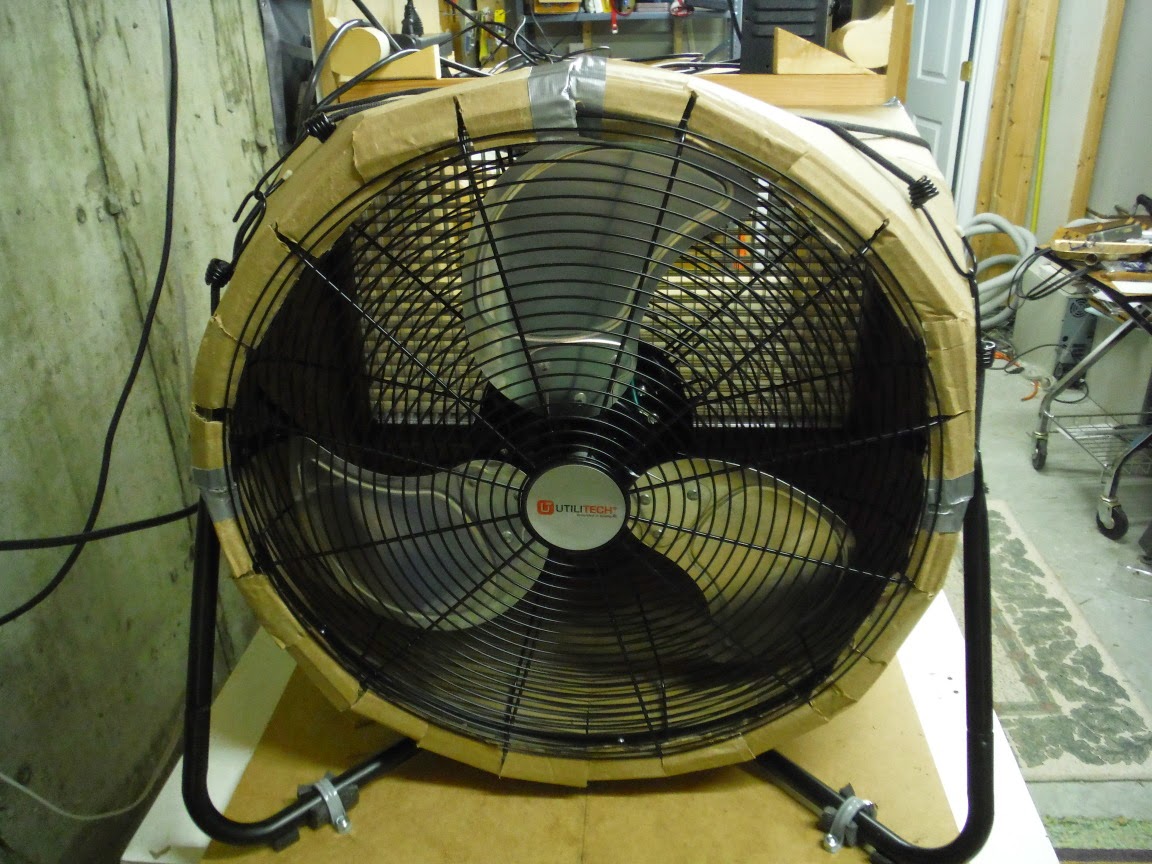
 Working on the wind-tunnel, I noticed that wind blows outward from the fan only directly in front of the fan blades.  There is an inward flow from those areas not directly in front of the blades.  I created a new cowling which wraps around the perimeter of the fan to cut off flow from those areas. The result is a speed increase in the chamber from 3.6 m/s to 4.1 m/s, a 14% improvement!


In mapping the flow field in chamber it turns out that the boundary layer develops quickly with distance from the front edge.  This chamber will be barely large enough  for the 30cm x 30cm plate; its boundary layer will impinge on the leeward corners of the plate.

Monday, August 25, 2014

Convection Instrumentation

My first design for the plate heater involved building a 100+ Volt power supply.  Since then I have realized that by stacking two laptop power supplies, a 40.V supply could be had inexpensively.  Each supply is rated for 90.W, so they have ample power for the heater.  The maximum current the heater will draw is 2 Amps; in order to account for wire losses, the voltage across the heater will be sensed by another pair of wires.

The first design had a digital-to-analog converter driving the gate of a SD220 n-channel MOSFET, and its output driving the gate of an IRF9520 p-channel power MOSFET.  The forward gain of the circuit was over 1000.  With such high gain, only a few of the DAC codes would cover the range of planned drive levels for the heater.  So I have ballasted both MOSFET source terminals with resistors to lower their gains.  The SD220 guarantees its threshold only to be less than 3.V, but the STM32F303VCT6 microcontroller DAC output only drives up to 2.8.V, so an op-amp is needed to servo the source resistor to the DAC output voltage.  Servoing the IRF9520 current to be proportional to the SD220 current means that, within its operating range, the current is set by the DAC.  Multiplying that current by the voltage sensed across the heater measures the power delivered to the heater.

The design includes electronic temperature, humidity, and air pressure sensors.  The only relevant condition not being sensed is windspeed in the chamber.  I investigated many windspeed sensing technologies, but techniques for measuring below 4.m/s require laminar flow, affect the flow, are too large, are inaccurate or are prohibitively expensive.

With a variable transformer I measured consistent windspeeds in the tunnel from 4.m/s down to 1.m/s.  The windspeed varies smoothly with the rotation rate of the fan.  Instead of trying to servo the fan's rotation rate, I will measure the rate of the fan blades interrupting an infrared beam between a LED and photo-transistor on opposite sides of the fan.  Calibrating the relation between windspeed (as measured by an impeller anemometer) and the fan's rotation rate will enable tracking of windspeed over small variations in rotation rate.
Saturday, August 2, 2014

Wind Tunnel Success!

My first tests of the wind tunnel were not encouraging.  This morning I turned the fan around so that it draws air through the wind tunnel instead of blowing (I left the egg-crate between the test chamber and fan cowling) and the results were excellent!

At the open end of the test chamber the flow rate was uniformly 3.6 to 3.7 m/s.  Taking measurements at the walls at increasing distance into the chamber, the flow rate gradually dropped as would be expected for the developing boundary layer.   Rotation in the test chamber was nearly unmeasurable.

Because the fan switch is now inside the cowling, I set the switch to its highest setting and plugged the fan into a variable autotransformer.  Adjusting it so that the pitch of the fan dropped about one octave (1/2 frequency), the flow rate dropped to 2.1 m/s, slightly more than half.  So the flow rate is a roughly linear function of fan speed.  I intend to put an opto-interrupter sensor on the fan to monitor its speed precisely.

I also ran a test without the egg-crate.  Uniformity was not as good, and there seemed to be some rotation in the test chamber.

Because I can't achieve 10 m/s in the tunnel, I must make my convection measurements at lower speeds.  This means that I must get more accurate measurements and estimates for the other modes of heat transfer than if the speed were higher (in order to achieve the same experimental accuracy).  Lower speeds also mean less heat flow; so the block of aluminum I bought for the plate is thicker and will have longer settling times than is needed.


Here is the tunnel in operation with the anemometer showing 3.7 m/s: